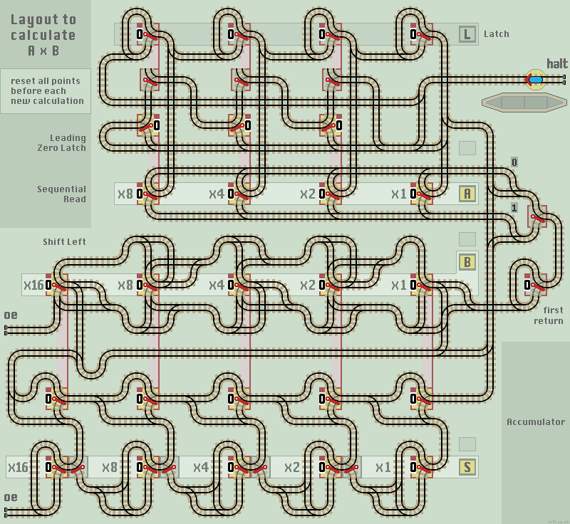
Multiply AxB (shift reg)
This circuit multiplies two binary numbers, held in input registers A and B, and outputs the result in register S. It uses a Shift Left and an Accumulator function to add successive multiples of 2. Read more at Wikipedia on binary number multiplication.
The circuit uses a Leading Zero Latch function to avoid unnecessary shift lefts of register B. This wastes time and can cause the register to overflow on the last cycle. Therefore the circuit works like this:
- First, check register A and latch any leading zeros to 1.
- Then, from the LSB, set each latch in turn, before passing down to read each digit in register A:
if it is 0 then shift left register B.
if it is 1 then shift left register B and add to register S. - Loop back and check the latch for the next digit. If all latches are set to 1 then halt the computation.
Just one problem. We need to supress the first shift left of register B. A 'first return latch' (below the station) returns the train on its first visit, so preventing a shift left when the LSB is read. All subsequent trains pass through to shift register B left.
Also below the station is a second passive lazy point. It ensures that a train returning back from the shift left function is directed to the accumalator if it originated from reading a 1 in register A.
We require 4 functions stacked in this order to make linking points easier:
- Sequential Read function
- Leading Zero Latch
- Shift Left function
- Accumulator function
Operation
Reset points in registers L and S, and the 'first return' to 0. Enter the two numbers to be multiplied (eg 5x6 or 3x10) into registers A and B. When the train returns to the station platform, read the computed output from register S.
Notes
- Multiplication is commutative, so AxB = BxA. A quicker calculation is obtained if the shorter number is entered into the A register, as there are fewer shift lefts to be carried out.
- If A=0 then the calculation terminates quickly. If B=0 then it must shift left for each digit in A.
- The shift left function inserts trailing 0's.
|
| Click layout to pause/run train | Click points to switch 0/1 | Click start circle to reset train/points |
| Lazy points switch between upper 0 or lower 1 branch lines Trains arriving on a branch line switch the point to that line |
|
| Sprung points allow branch line trains to join the main line All main line trains go straight ahead and never 'branch off' |
If the input registers A and B are linked together, then the circuit acts as a 'squared' maths function producing A x A.
The layout could be modified to produce the factorial function. By including a Counter, the sum could be multiplied by an incremented count each cycle. Factorial numbers increase rapidly, 5! = 120.